Understanding the Clock Subsytem
As mentioned, the vendor provides a repo of examples for their various chips. You can study them to use the various peripherals. So we won't repeat them here. But we'll discuss one crucial component - the clock.
One peculiarity of these Si-Labs chips (at-least the efr32Xg21 family) is they take a fixed 38.4MHz crystal for the external source. This simplifies a lot of the clock setup configs.
Here is a basic diagram with the most used components.
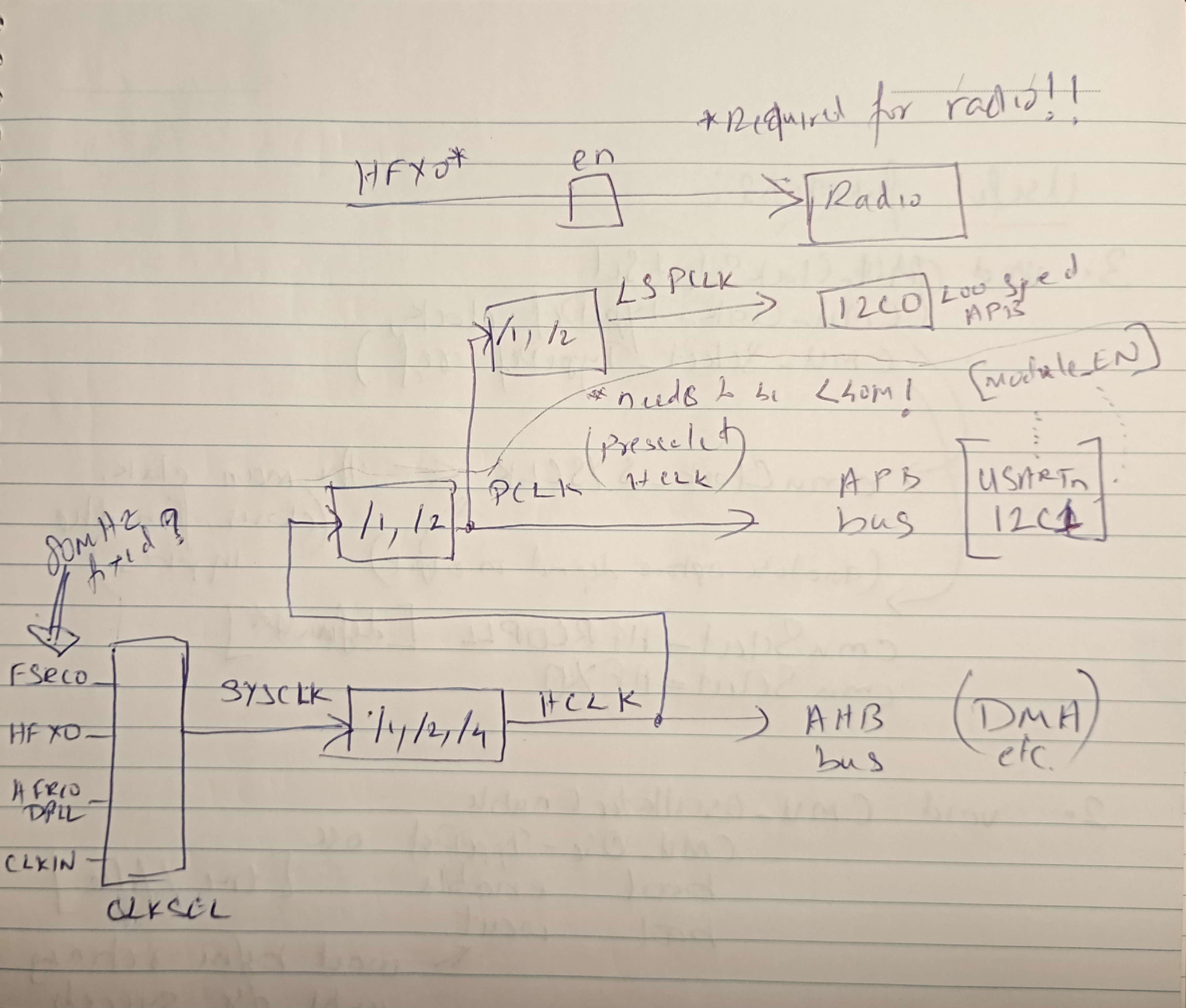
Note that the chip boots on FSRCO then switches to HFRCODPLL before executing user firmware.
Setting up for external crystal
Our ZYZBP008 module comes with an external crystal attached (according to the datasheet, it is mandatory to source from the external clock to enable the radio unit). Here is a code excerpt from the example repo on how to configure for the external source:
#include "em_cmu.h"
#include "em_chip.h"

int main(void)
{
  CHIP_Init();

  // Start the HFXO with safe default parameters
  CMU_HFXOInit_TypeDef hfxoInit = CMU_HFXOINIT_DEFAULT;
  CMU_HFXOInit(&hfxoInit);
  CMU_OscillatorEnable(cmuOsc_HFXO, true, true);
  //                            enable^     ^wait until clock succeeds before returning

  // Switch the SYSCLK to the HFXO.
  CMU_ClockSelectSet(cmuClock_SYSCLK, cmuSelect_HFXO);

  while(1);

  return 0;
}
Lookup for these functions and their possible options in the clock component documentation. CMU_HFXOINIT_DEFAULT is defined in em_cmu.h and apparently suitable in most usual cases.
To verify that it works, we will test the UART peripheral (which is time sensitive).
#include "em_cmu.h"
#include "em_chip.h"
#include "em_gpio.h"
#include "em_usart.h"

#define BSP_BCC_TXPORT  gpioPortA // A05 - TX
#define BSP_BCC_TXPIN   5 //
#define BSP_BCC_RXPORT  gpioPortA // A06 - RX
#define BSP_BCC_RXPIN   6 //

int main (void)
{
  CHIP_Init();

  // Start the HFXO with safe default parameters
  CMU_HFXOInit_TypeDef hfxoInit = CMU_HFXOINIT_DEFAULT;
  CMU_HFXOInit(&hfxoInit);
  CMU_OscillatorEnable(cmuOsc_HFXO, true, true);

  // Switch the SYSCLK to the HFXO.
  CMU_ClockSelectSet(cmuClock_SYSCLK, cmuSelect_HFXO);

  CMU_ClockEnable(cmuClock_GPIO, true);
  GPIO_PinModeSet(gpioPortA, 0/*pin 4*/, gpioModePushPull /*push-pull output*/, 1/*output level*/);

  CMU_ClockEnable(cmuClock_USART0, true);

  USART_InitAsync_TypeDef initAsync = USART_INITASYNC_DEFAULT;
  initAsync.baudrate = 115200;

  GPIO->USARTROUTE[0].TXROUTE = (BSP_BCC_TXPORT << _GPIO_USART_TXROUTE_PORT_SHIFT)
            | (BSP_BCC_TXPIN << _GPIO_USART_TXROUTE_PIN_SHIFT);
  GPIO->USARTROUTE[0].RXROUTE = (BSP_BCC_RXPORT << _GPIO_USART_RXROUTE_PORT_SHIFT)
            | (BSP_BCC_RXPIN << _GPIO_USART_RXROUTE_PIN_SHIFT);

  GPIO->USARTROUTE[0].ROUTEEN = GPIO_USART_ROUTEEN_RXPEN | GPIO_USART_ROUTEEN_TXPEN;
  USART_InitAsync(USART0, &initAsync);

  GPIO_PinModeSet(BSP_BCC_TXPORT, BSP_BCC_TXPIN, gpioModePushPull, 1);
  GPIO_PinModeSet(BSP_BCC_RXPORT, BSP_BCC_RXPIN, gpioModeInput, 0);

  //USART_Tx (USART_TypeDef * usart, uint8_t data)

  char buf[] = "Hello";

  while(1) {
    GPIO_PinOutToggle(gpioPortA, 0/*pin 4*/);

    for (int i = 0; i < 6; i++) {
      USART_Tx (USART0, buf[i]);
      USART_Tx (USART0, '\n');
    }

    for (volatile uint32_t i = 0; i < 100000; i++) { } // busy delay
  }

  return 0;
}
The above code should print Hello via serial repeatedly with the roughly specified pauses.